Course Content
- Review of circuit analysis
- Brief introduction to semiconductors. PN junction, diode circuit
- Single stage BJT and FET amplifiers
- Multiple stage amplifiers
- Discrete differential amplifier
- Amplifier models
- Operational amplifier circuit
- Others
Revision Of Circuit Theory
Passive Reference Configuration
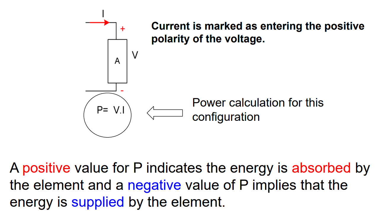
This results in the current entering the positive terminal of the voltage.
Kirchhoff’s Laws
There are two Kirchhoff’s Laws; Kirchhoff’s Voltage Law and Kirchhoff’s Current Law.
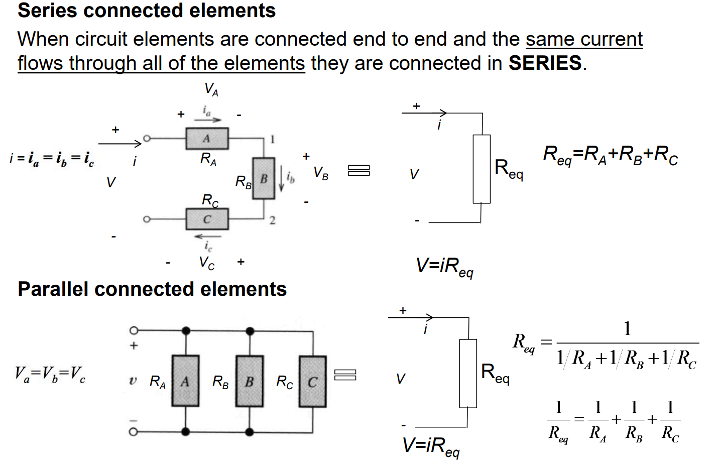
Series and Parallel Circuits
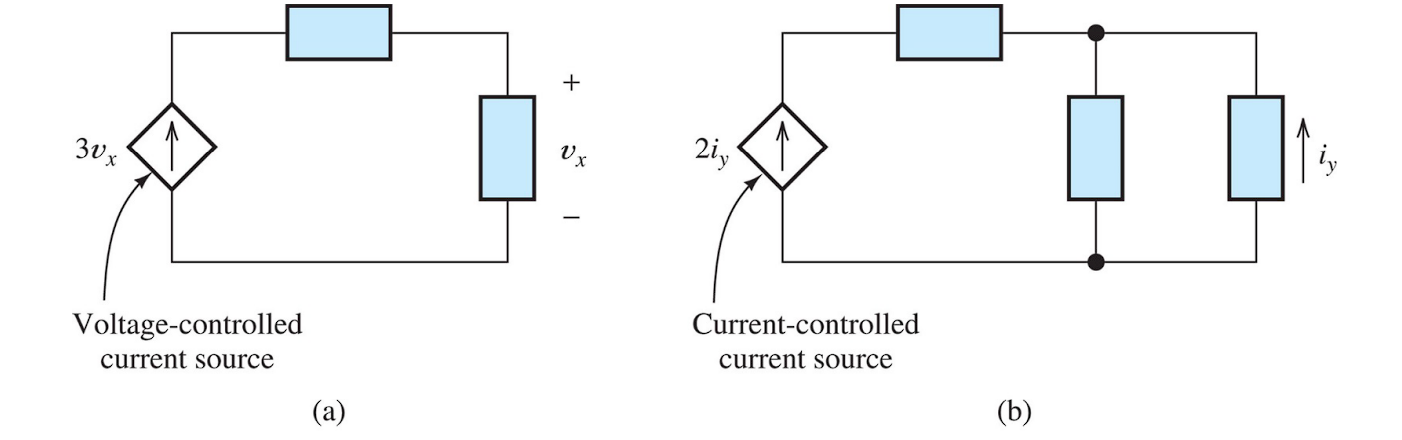
Independent and Dependent Sources
There are many independent and dependent voltage and current sources, depending on the components that control each part.
Dependent Voltage Sources
Dependent Voltage Sources (also known as controlled voltage sources) are represented by diamond shaped symbols. The voltage across a dependent voltage source depends on the current or voltage that appears elsewhere in the circuit.
Current Divider Circuit
For two resistances in parallel, the fraction of the total current flowing in a resistance is the ratio of the other resistance to the sum of the two resistance. This is known as the Current division principle. This only applies to two resistors.
For more than two resistors in parallel, you need to first combine some resistors in order to get two resistors only.
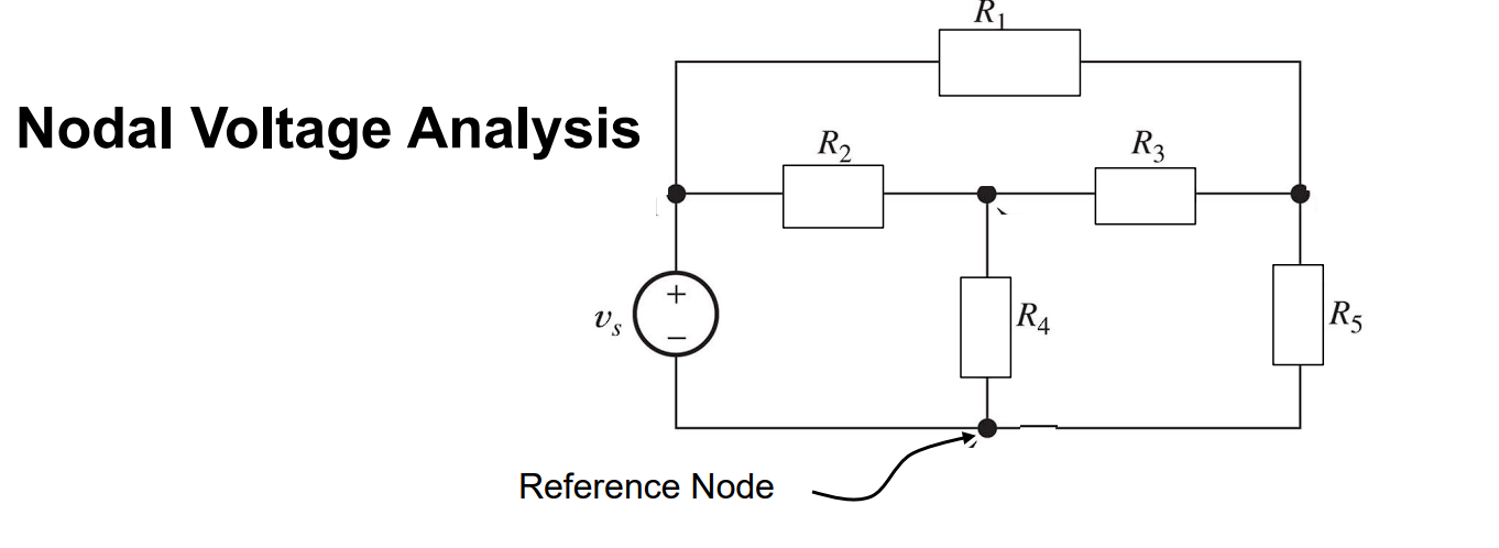
Nodal Analysis Techniques
Steps to Complete Nodal Analysis
Step 1 - Identifying Nodes and Selecting the Reference Node
- Identify the nodes in the circuit
- Select one of the nodes as the reference node - Typically one end of the source (Mostly negative terminal of the voltage source.)
- Reference node has a negative polarity with respect to nodes
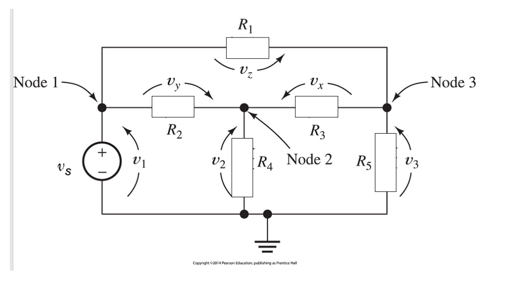
Step 2 - Assigning Node Voltages
- Label the voltage of each nodes except for the reference node.
- Node Voltages are positive with respect to reference voltage.
- Reference Node has a negative polarity with respect to nodes.
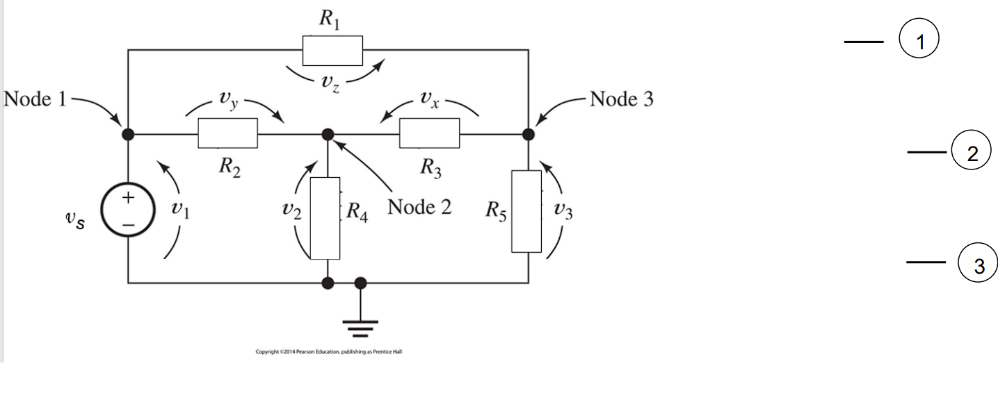
Step 3 - Writing KCL Equations in terms of the Node Voltages and Solve for Unknowns
- Apply KCL to all unknown nodes (avoid nodes that are connected to voltage sources.)
- How many unknown nodes are there?
- How many unknown equations are required to solve for the unknowns?
Mesh Current Analysis
Steps to Complete Mesh Analysis
Step 1 - Choosing the Mesh Currents
- Choose a planar circuit (if necessary redraw without crossing conductors or elements)
- Choose the current variables as a mesh current which flow through the elements around the periphery of each of the open area of the circuit diagram
- Direction of the current - typically clockwise.
Step 2 - Write Network Equations
- First use KVL to write voltage equations for meshes that do not contain current sources.
Solve Network Equations
- Use determinants (Matrix form) or other means
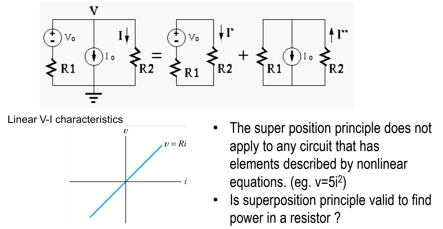
Superposition Principle
For all linear systems, the net response at a given place and time caused by two or more stimuli is the sum of the responses which would have caused by each stimulus individually.
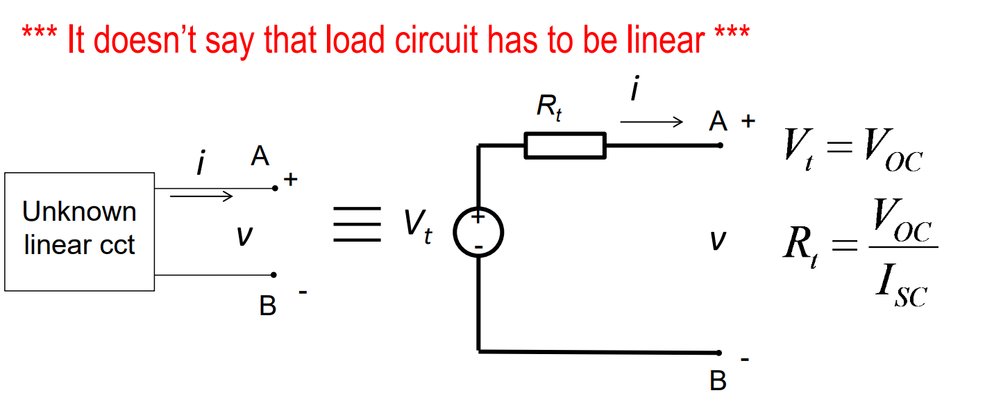
Thevenin Equivalent Circuit
Thevenin’s Theorem
If the source circuit in a two-terminal interface is linear, then the interface signals and do not change when the source circuit is replaced by its Thevenin equivalent.
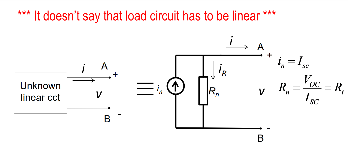
Norton’s Equivalent Circuit
Norton’s Theorem
If the source circuit in a two-terminal interface is linear, then the interface signals and do not change when the source circuit is replaced by its Norton equivalent.